Rebuilding a Robot
Moving a robot from Arduino to Raspberry Pi
Intro
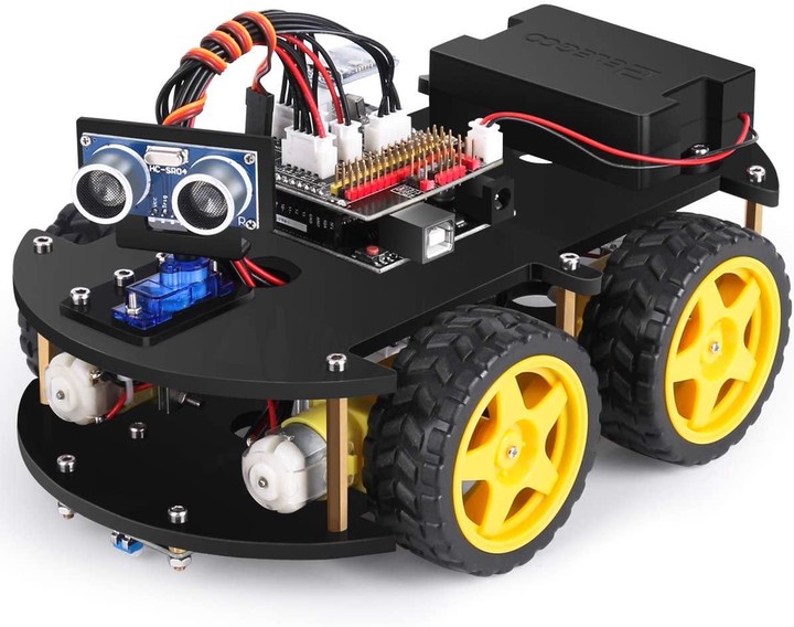
A couple of Christmases ago, I received an ELEGOO UNO R3 Project Smart Robot Car from my family as a gift. I thoroughly enjoyed assembling it and playing around using the included remote control or the app it has for Bluetooth. While Arduino is a fairly robust platform, I wanted something that I felt more comfortable controlling. Enter: Raspberry Pi.
Out of the box, the Smart Robot Car is well equipped:
- Ultrasonic Sensor for detecting objects and obstructions
- Triple-sensor line following module
- Bluetooth (BLE) on board
- Infra-red receiver and remote control
- Intelligent power pack to charge and maintain two 18650 Lithium batteries
- Android/iPhone App for controlling and using “block” language
- Pre-configured Arduino UNO with code to drive, use object detection, line-following, and manual driving
Some of the things that I felt were missing:
- Ability to extend it outside the pre-fabricated boards made by ELEGOO
- Video for object/face/etc. detection
- The ability to use other software platforms, like Python to program the car
Getting Started
Specs
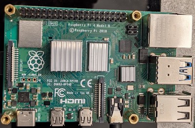
I went with a Raspberry Pi 4b, 8GB edition. This is overkill! It just happened to be the Pi I already had on hand. If I need to take the robot apart in the future, I might swap it for a 3, or at least a 4b with less memory. I bought it as a part of a Starter Kit from CanaKit. I did this because, at the time, I intended on using it as a desktop. It is running the standard Raspberry Pi OS. The Wifi is enabled and Secure Shell is the primary access method (although the full desktop is still enabled).
Prerequisites
I wish I could say retrofitting a Raspberry Pi on a robot previously configured for Arduino is easy, but it’s not. Off the top, here are a few things I had to reconfigure or adjust:
- Bore new/different holes into the two acrylic platforms to hold the Raspberry Pi and the motor HAT.
- Obtain M2 head cap bolts and nuts to replace some of the larger bolts supplied with the original kit.
- The original kit provided a motor controller board attached to the lower platform. I wanted to keep that design decision, so I had to buy some 40-pin ribbon cable to ensure I could interface the motor HAT even though the Pi and other accessories remained on the upper platform.
- Purchased additional varying sizes of both male and female JST connectors and pigtails. This method allowed me to reuse existing cabling and not cut/modify any of the original components.
Purpose
I needed to decide what I wanted to do with it beyond what the Arduino would provide to build the robot. The central piece for me was to attach a camera to identify objects more accurately. There are many examples of leveraging OpenCV for facial recognition. The original bot comes with an ultrasonic sensor, which is adequate for basic sensing but has some limitations overcome by vision and object detection.
The other requirement: ensure that ALL of the original components are connected to the Raspberry Pi the same way as they were with the Arduino controller. This concern would require some extra work and ultimately building a custom HAT to support both the ultrasonic sensor and the line detection modules. The Robot Car includes a reasonably usable app for Android and iOS to control and even use block language to develop rudimentary programs. I wanted to provide enough backward compatibility so that the app would work.
The Build
The Motor HAT
The first order of business required acquiring and testing to ensure the motors would run with the Raspberry Pi. I selected the Adafruit DC+Stepper motor HAT. It drives up to four DC motors or two stepper motors. It also will control up to four servo motors. This HAT proved valuable as I needed a servo controller to drive the ultrasonic sensor’s left-to-right motion.
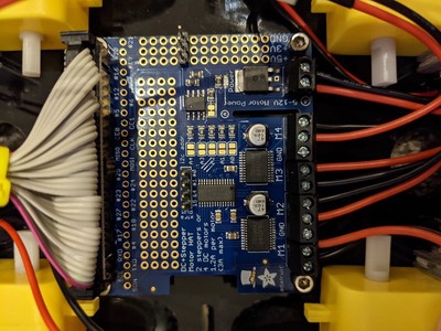
Before proceeding too far down the path, I connected the motor HAT to the Pi and the battery pack to determine if it would work. The video below shows that this seemingly would work.
The Custom Sensor HAT
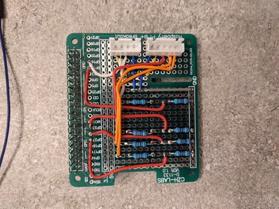
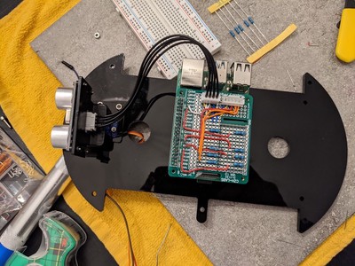
The second challenge was to develop a way to use the original kit sensors. Beyond the ability to use the sensors, I didn’t want to cut or otherwise damage any original connectors or wires. Furthermore, the Raspberry Pi GPIO tends to deliver and expect 5 volts, whereas the Arduino sensors require 3.3 volts. This situation meant creating a set of voltage dividers to reduce the current sent to the sensors. Several different prototyping boards are available. This breakout board suited my purposes well.
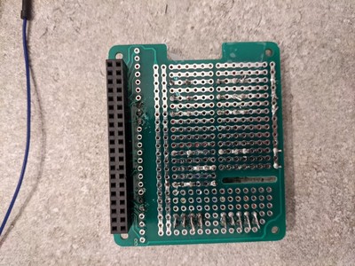
I won’t get into the details here, but creating voltage dividers requires the use of different resistors to draw enough current away from the components to meet their needs without frying them. I needed a voltage divider for the ultrasonic sensor and one for each of the line detection sensors on the bottom of the car. This was a good experience for me, as I had never really soldered an actual circuit board before.
The Pan and Tilt HAT
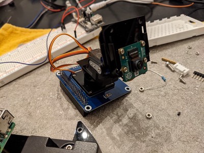
I needed a way to mount the camera. The robot car kit did not have an obvious way to do that, and I don’t own a 3D printer to manufacture a custom mount. I opted for the Waveshare Pan-Tilt HAT. This was an unexpected bonus because I would be able to turn the camera and look in a multitude of directions with it.
Building the Robot
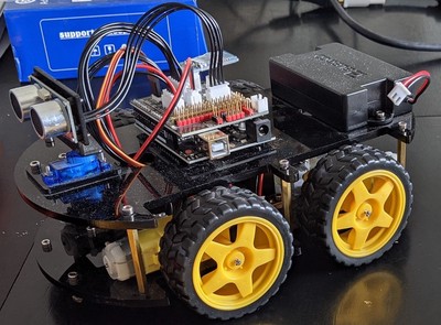
Once I had the holes drilled, the suitable screws, and nuts, the assembly began.
The lower platform contains the motors and the motor hat. The Arduino version had the motor controller board on the lower platform, so I used a ribbon cable to keep the Pi-equivalent motor HAT and the motor power connectors underneath.
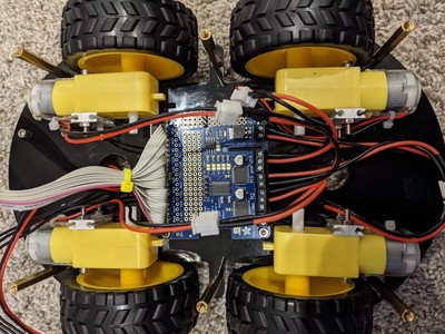
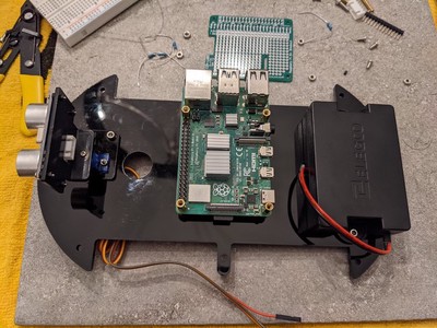
On the upper platform, the Raspberry Pi is attached directly. Of course, I didn’t consider the size differential between the Arduino and the Pi, so it is mounted off-center.
The breakout board for the ultrasonic and line detecton sensors is next.
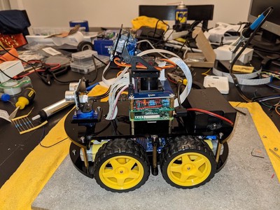
The pan and tilt HAT went on last. Below is the car fully assembled, complete with a camera and power supply.
As always, it’s essential to stop and test things along the way. Below is a quick clip of the servo motors rotating the ultrasonic sensor and the pan and tilt arm.
What’s Next?
- WRITING SOME ACTUAL CODE! I now have some basic scaffolding to propel the robot forward, view the camera output, and spin the servos. So much more work to do.
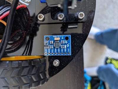
- Add a gyroscope. I want to detect the direction and directional drift of the robot while it is driving.
Final Thoughts
I’m glad I did this. I learned more about the lower layers of robotics hardware beyond the VEX IQ or LEGO kits. I determined I’m pretty good at soldering but could use some more practice. I also gained confidence in “hacking” something together from effectively nothing. It’s a great little toy, and much more learning will occur with it.
Thanks for tagging along with me!